12.1 CURRENT AND CHARGE
- To make an electric current pass around a circuit, it must be complete + include a source of potential difference, such as a battery.
- Current is the rate of the flow of charge in the wire or component.
- The current is due to the passage of charged particles:
- Charge carriers.
- The current is due to the passage of charged particles:
- In metals, the charge carriers are conducting electrons, which move about inside the metal and collide with each other and the other positive ions in the metal.
- In salt solutions, the charge is carried by the ions, the charged atoms or molecules.
- A simple test for conduction is shown below:
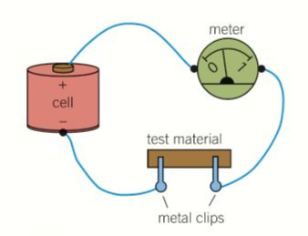
- The meter shows a non-zero reading whenever any conducting material passes through the circuit.
- The battery forces the charge carriers through the conducting material, through the battery & meter.
- Electrons enter at positive and leave at negative.
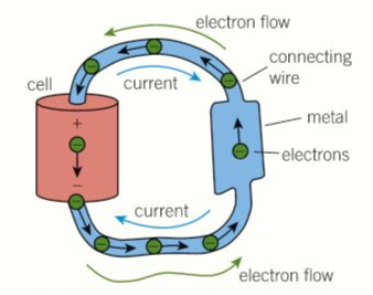
- This is explained well below:
Conventional Current assumes that current flows out of the positive terminal, through the circuit and into the negative terminal of the source. This was the convention chosen during the discovery of electricity. They were wrong!
Electron Flow is what actually happens and electrons flow out of the negative terminal, through the circuit and into the positive terminal of the source.
- The unit of current: Amperes (A)
- Defined as the magnetic force between two parallel wires when they carry the same current. Given by “I”
- The unit of charge: Coulomb (C)
- Defined as the charge flow in one second when the current is one ampere. Given by “Q”
- ΔQ = IΔt
- I= ΔQ/Qt
- For example, the charge flow for a current of:
- 1A in 10 seconds is 10C
- 5A in 200 seconds is 1000C
- 10mA in 500 seconds is 5C
- The equations above shows that a current of 1 A is due to a flow of charge of 1 Coulomb per second.
- The magnitude of the charge of the electron is 1.6×10⁻¹⁹
- Therefore, a current of 1A along a wire must be due to 6.25×10¹⁸ electrons per second.
More about charge carriers:
- Insulator:
- Each electron is attached to an atom and cannot move away from the atom.
- When a voltage is applied, no current passes through the insulator because electrons cannot move through it.
- Metallic conductor:
- Most electrons are attached to atoms but some are delocalised.
- The delocalised electrons are the charge carriers in the atom.
- When a voltage is applied across the metal. these conduction electrons are attracted to the positive terminal of the metal.
- In a semiconductor:
- The number of charge carriers increases with temperature of the metal.
- The resistance decreases as temperature increases.
- A pure semi-conducting material is referred to an intrinsic semiconductor.
- Because conduction is due to electrons that break free from the atoms of the semiconductor.
12.2 POTENTIAL DIFFERENCE AND POWER:
Energy and potential difference:
- When a torch is connected to a battery. the electrons delivery energy from the battery to the bulb.
- Each electron moves around the circuit and takes a fixed amount of energy from the battery as it pass through it.
- Delivers energy to the bulb and back to the positive terminal to be resupplied with energy.
- A battery has the potential to transfer energy from its chemical state if the battery is not part of a complete circuit.
- When the battery is connected to the circuit, each electron does work to pass through the component and therefore transfers some or all of its energy.
- The work done by an electron = Loss of energy.
- Work done per unit of charge is potential difference.
- PD is work done per unit of charge
-
Example:
-
30J at 5 C of charge, the voltage = 6V
- EMF of a source of electricity is the electrical energy produced per unit of charge passing through the source.
- Unit for EMF= Volts
- Electrical energy produced when charge Q passes through the source = QΕ
Energy transfer in different devices:
- An electrical current has a heating effect when it passes through a component with resistance.
- Also has a magnetic effect wheich is made use of in electric motors and loudspeakers.
- In a device that has resistance, such as an electric heater, the work done on the device is transferred as thermal energy.
- The charge carriers repeatedly collide with atoms in the device and transfers energy to them, the atoms vibrate more and becomes hotter.
- In an electric motor. turning at a constant speed, the work done on a motor is = energy transferred to the load and surroundings by the motor
- Therefore, the kinetic energy of the motor remains constant.
- Charge carriers are electrons that force themselves through the wires of the spinning motor coil against the opposing force on the electrons due to the motor’s magnetic field.
- For a loudspeaker, the work done is transferred as sound energy.
- The electrons need to be forced through the wires of the vibrating loudspeaker coil against the force on them due to the loudspeaker magnet.
Electrical power and current:
- A device that has a pd of “V“across its terminals and a current of “I” passing through it, in time Δt:
- The charge flow through it:
- The work done by the charge carriers:
- The charge flow through it:
- Therefore Work Done:
- The energy transfer: ΔE in the component or device is equal to the work done.
- Power = Energy/Time
- Therefore, the electrical power P supplied to the device is:
- Therefore:
- Unit of Power is the Watt
12.3 RESISTANCE:
Definitions and laws:
- Resistance of a component in a circuit is a measure of difficulty of making current pass through it.
- Resistance is caused by the repeated collisions between the charge carriers in the materia; with each other and the fixed positive ions in the material.
- Resistance of any component: PD across the component/ Current through it.
- Unit is the Ohm (Ω)
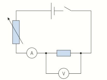
Measurement of resistance: (Practical)
- A resistor is a component designed to have a certain resistance, constant no matter what the current is.
- Ammeter is used to measure the current through the resistor, must be in series.
- Voltmeter is used to measure the potential difference across the resistor, must be in parallel.
- No current must pass through the voltmeter otherwise the ammeter will not record the exact current through the resistor.
- The voltmeter should have infinite resistance.
- The variable resistor is used to adjust current and pd.
- Used to change them and record the results for each change in resistance,
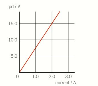
- The graph for a resistor is a straight line from the origin.
- Resistance is the same regardless of current.
- The gradient is resistance
Ohm’s law:
Ohm’s law states that the PD across a metallic conductor is proportional to the current through it, provided the physical conditions do not change.
Some side-notes on Ohm’s law
- Ohm’s law is the equivalent statement that the resistance of a metallic conductor under constant physical conditions, such as temperature, is constant.
- For an ohmic conductor, V= IR, where R is a constant, A resistor is a component designed to have a certain resistance.
- If the current and PD measurements for an ohmic conductor are plotted with current on the Y-Axis and PD on the X-axis, the gradient gives 1/R
Resistivity:
- For a conductor of length L and uniform cross-sectional area A, as shown below, its resistance R is:
- Proportional to L
- Inversely proportional to A
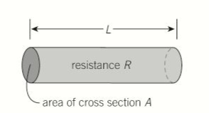
- Therefore
- Therefore Resistivity:
- The unit for resistivity is the ohm metre
- For a conductor with circular cross section of diameter d:
Finding resistivity of a wire:
- Measure the diameter of the wire d, a micrometer at several different points to find a mean value for d to calculate the area.
- Measure the resistance R for different lengths L of wire to plot a graph of R against L
- The resistivity of the wire is given by the gradient of the graph × area

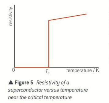
Superconductivity:
How it works:
- Device or a wire made of a material that has zero resistivity at and below a critical temperature that depends upon the material itself.
- The property is called superconductivity.
- The wire has a zero resistance below the critical temperature.
- When current passes through it, there is no PD across it because resistance= 0
- Therefore the current has no heating effect.
Properties of a superconductor:
- Loses its superconductivity if its temperature is raised above critical temperature.
- Highest critical temperature is -123°
Uses:
- High powered electromagnets
- Generate very strong magnetic fields in devices like MRI scanners and particle accelerators.
- Used in the development of lightweight electric motors and power cables that transfer energy without energy dissipation.
12.4 COMPONENTS AND THEIR CHARACTERISTICS:
Circuit diagrams:
- Cell:
- A device, such as a battery, that is capable of changing some formof energy, such as chemical energy or radiant energy, intoelectricity.

- Ammeter:
- An instrument for measuring electric current in amperes.

- Voltmeter:
- An instrument used for measuring electric potential in volts.

- Indicator or lightsource:
- A device used to produce a source of illumination.

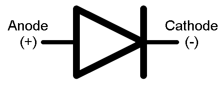
- Diode:
- A semiconductor device with two terminals, typically allowing the flow of current in one direction only due to the very high resistance in the other direction.
- Light-emitting diode:
- A light-emitting diode (a semiconductor diode which glows when a voltage is applied).

- Resistor:
- A resistor is an electrical component that limits or regulates the flow of electrical current in an electronic circuit. Resistors can also be used to provide a specific voltage for an active device such as a transistor.


- Variable resistor:
- An electronic component that is used to vary the amount of current that flows through a circuit. It works by sliding a wiper terminal across a resistive material, typically a thin film or chunk of carbon or a resistive wire made of nickel chromium or tungsten alloys.


- Thermistor:
-
An electrical resistor whose resistance is greatly reduced by heating, used for measurement and control.


-
- Light dependant resistor:
- An LDR is a component that has a (variable) resistance that changes with the light intensity that falls upon it. This allows them to be used in light sensing circuits.
-


- Heater:

Investigating the characteristics of different components:
- To measure the variation of current with pd for a component, use either:
- A potential divider to vary the pd from 0r a:
- Variable resistor to vary the current to a minimum
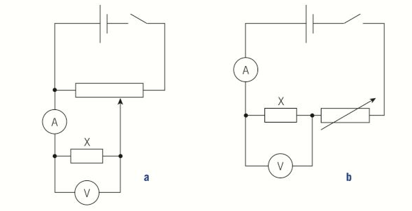
- The advantage of using a potential divider is that the current through the component and the pd across it can be reduced to zero, which is not possible through a variable resistor circuit.
- The measurements for each type of component can be plotted against a graph of current against pd.
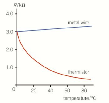
- Typical graphs for a wire, filament lamp and a thermistor are shown people.
- The measurements are the same regardless of which way the current passes through the components.
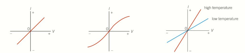
- A wire gives a straight line through the origin.
- The value of V/I is the same on any point of the wire.
- The resistance does not change
- A filament bulb gives a curve with a decreasing gradient because resistance increases with temperature.
- A thermistor at constant temperature gives a straight line.
- The higher the temperature, the steeper the gradient, therefore the lower the resistance.
- The same result is obtainable through an LDR.
The diode:
- When investigating the characteristics of diode, one set of measurements is made in the forward direction, and another set in the reverse direction.
- The current is very small when reversed and can only be measured with a milliammeter.
- Typical results for a diode are shown below, a silicon diode conducts easily in the forward direction above a pd of 0.6V and barely any below 0.6V

Resistance and temperature:
- Resistance of a metal increases with increase in temperature.
- Because of the positive ions in the conductor vibrate more when its temperature is increased.
- The charge carriers therefore cannot pass through the metal as easily when a pd is applied across the conductor.
- A metal is said to have a positive temperature coefficient when resistance increases with an increase of temperature.
- The resistance of an intrinsic semiconductor decreases with an increase of temperature.
- The number of charge carriers increase when the temperature is increased.
- A thermistor made from an intrinsic semiconductor therefore has a negative temperature coefficient.