
13.1 CIRCUIT RULES:
Current rules:
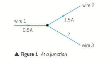
- At any junction in a circuit, the total current leaving the junction = total current entering the junction.
- The junction rule holds because the rates of charge flowing in and out of a junction are always equal.
- Charge entering the junction = 0.5C along wire 1, and the 1C along wire 3.
- The charge leaving the junction each second must be therefore 1.5C as the junction.
- Components in series:
- Current entering a component is the same as the current leaving the component.
- The components does not use up the current. The charge per second entering a component = charge per second leaving a component.
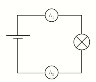
- Both ammeters show the same value for current.
- The Current passing through two or more components in series is the same through each component.
- Rate of flow of charge through each component is the same at any moment of time.
- The same amount of charge passing through any one component each second passes through the other component each second.
- Current entering a component is the same as the current leaving the component.
Potential difference rules:
Potential difference between any two points in a circuit is defined as the energy transfer per coulomb of charge that flows from one point to another.
- If the charge carriers lose energy, the potential difference is a potential drop.
- If the charge carriers gain energy, which happens when they pass through a battery or cell.
- Potential difference is a potential which is = the potential difference across the battery or cell.
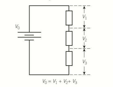
- For two or more components in series, the total pd across all the components is equal to the sum of the pd across each component.
- The diagram below shows the battery terminals is equal to the sum of the pd across the three resistors.
- This is because the pd across each resistor is the energy delivered per coulomb of charge to that resistor.
- Sum of the potential difference across the three resistors is the total energy delivered to the resistors per coulomb of charge passing through them, pd across the battery terminals.
- PD across components in parallel is the same.
- In the diagram below, the charge carriers can pass through either of the two resistors in parallel.
- Same amount of energy is delivered by a charge carrier regardless of which of the two resistors it passes through.
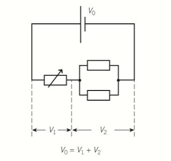
- If the variable resistor is adjusted so that the pd = 4V, if the battery pd is 12V, the pd across each resistor in parallel =8V (=12V-4V)
- Each coulomb of charge leaves the battery with 12J of electrical energy and uses 4J from passing through the variable resistor.
- Therefore each coulomb of charge has 8J of energy to deliver to each of the 2 parallel resistors.
- For any complete loop of a circuit, the sum of the emfs around the loop is equal to the sum of the potential drops around the loop.
- Total emf in a loop is the total electrical energy per coulomb of charge in the loop and the sum of the potential drops is the electrical energy per coulomb delivered around the loop.
- The statement follows therefore from the conservation of energy.
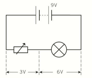
- In the diagram below, the battery has an emf of 9V, the variable resistor is adjusted so that the pd across the light is 6V
- Therefore the pd across the variable resistor is 3V
- Therefore total emf: 9V.
- Every coulomb of charge leaves the battery with 9J of electrical energy and supplies 3J to the variable resistor and 6J to the light.
Each time a charge carrier goes around the circuit:
- A certain amount of energy “E” is transferred to it from the battery.
- It transfers energy equal to E/3 to the variable resistor, and 2/3E to the light bulb.
13.2 MORE ABOUT RESISTANCE:
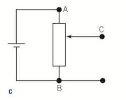
Resistance in series:
When resistor in series pass the same current, the total pd is = sum of all pds.
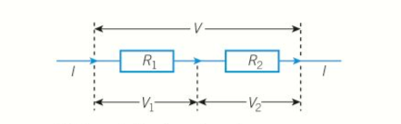
- For two resistors R1, R2 in series, as shown above, when current I passes through the resistors:
- Pd across R1, V1=IR1
- Pd across R2, V2=IR2
- Total Pd=IR1+IR2
- For two or more resistors R1+R2+R3 in series, the theory can be easily extended to show that the total resistance = sum of the individual resistances.
- R=R1+R2+R3+…….
Resistors in parallel:
- Resistors in parallel have the same voltage.
- Current through a parallel combination of resistors is equal to the sum of the individual currents.
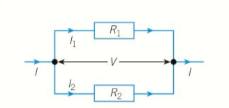
- For two resistors R1 and R2 in parallel, as in figure 2, when the pd across the combination is V:
- The current through R1,
- The current through R2,
- Total current is:
- The current through R1,
- Total resistance in a parallel circuit:
- For two resistors R1 and R2 in parallel, as in figure 2, when the pd across the combination is V:
Resistance heating:
- Heating effect of an electric current in any component is due to the resistance of the component.
- Charge carriers repeatedly collide with the positive ions, and there is net transfer or energy from the charge carriers to the positive ions as a result of the collisions.
- After charge carriers lose kinetic energy in such a collision,
- the force due to the pd across the material accelerates it until it collides with another positive ion.
- For a component of resistance R, when current I passes through it, the pd across the component V=IR
- Power supplied :
- Energy transferred to the component per second as thermal energy:
- If the component is at a constant temperature, heat transfer =
- Rate of heat transfer:
- If the component heats up, the temperature rises depends upon the power supplied to it (
) and the rate of transfer heat to the surroundings.
- Energy transferred to the object by the electric current in time t=
- Energy transfer per second to the component does not depend on the direction of the current.
13.3 ELECTROMOTIVE FORCE AND INTERNAL RESISTANCE:
Internal resistance:
- Internal resistance: of a source of electricity is due to opposition to the flow of charge through the source
- Electrical energy produced by the source is dissipated inside the source when charge flows through it.
- Emf: (ε) of a source of energy per unit produced by the source.
- If the electrical energy supplied to a given charge in the source:
- Pd across the terminals of the source is the electrical energy per unit of charge delivered by the source when it is in a circuit.
- The terminal pd is less than the emf whenever current passes through the source, this is known as internal resistance.
- If the electrical energy supplied to a given charge in the source:
Internal resistance of a source is the loss of potential difference per unit of current in the source when current passes through the source.
- In circuit diagrams, internal resistance of a source can be shown as resistor symbol or labelled as internal resistance, the resistor is in series with the cell in the circuit.
- When a cell of emf ε and internal resistance r is connected to a resistor of resistance R as shown below, all the current through the cell passes through its internal resistance and the external resistor.
- Therefore the two resistors are in series which means that the total resistance =r+R.
- Therefore the current through the cell:
- In other ways, the cell emf:
- Therefore the current through the cell:
- The lost potential difference inside the cell is equal to the difference between the cell emf and pd across its terminals.
- In terms of energy, the lost pd is the energy per coulomb that is dissipated or wasted due to internal resistance.
Power:
- multiplying each term by the cell current I gives:
- Power supplied by the cell:
- The power supplied to the cell =power delivered to R + the power wasted in the cell due to internal resistance.
- Power delivered to R=
- Because :
- Because :
- The figure below shows how the power delivered to R varies with the value of R.
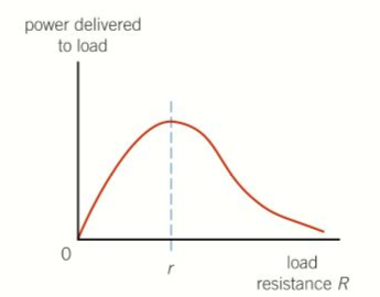
- It can be shown that the peak of the power curve is at R=r.
- In other words, when a source delivers power to load.
- Maximum power is delivered to the load when the load resistance is equal to the internal resistance of the source.
- The load is then said to be matched to the source
- Power supplied by the cell:
Measurement of internal resistance:
- The figure below shows how the terminal pd can be measured for different values of current.
- The pd across the terminals of a cell, when the cell is in a circuit, can be measured by connecting a voltmeter directly across the the terminals of the cell.
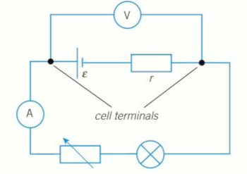
- The current is changed by adjusting the variable resistor.
- The lamp resists the maximum current that can pass through the cell.
- Ammeter is used to measure the cell current.
- Measurement of terminal pd and current in a cell can be plotted in a graph as shown below:

- The terminal pd decreases as the current increases, this is because the lost pd increases as the current increases.
- Graph is a straight line with a negative gradient.
- Can be done by rearranging the equation
- To make
- IR represents the terminal pd V
- Can be done by rearranging the equation
Notes:
- Internal resistance and the emf of a cell can be calculated if the terminal pd is known for two different values of current.
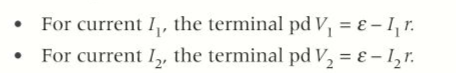

- Therefore r can be calculated from the above equation and then be subbed back into either equation for the cell pd to enable
to be calculated.
13.4 MORE CIRCUIT CALCULATIONS:
Circuits with a single cell and one or more resistors:
- Sketch the circuit diagram.
- To calculate the current passing through the cell, calculate the tal circuit resistance.
- Add on internal resistance if it is not negligible.
- Cell current = cell emf/total circuit resistance.
- Working out the current and pd for each resistor, start with the resistors in series with the cell, which therefore passes the same current as the cell current.
- PD across each resistor in series with the cell:
- =Current × resistance of each resistor.
- To work out the current through parallel resistors, work out the combined resistance and multiply the cell current to give the pd across each resistor.
- Current through each resistor= pd across the parallel combination/resistor’s resistance.
Circuits with cells in series:
- Same rules apply except the current through the cells is divided by adding the overall emf by the total resistance:
- If the cells are connected in the same direction in the circuit, the net emf is the sum of the individual emfs.
- If the cells are connected in opposite directions to each other, the net emf is the difference between the emfs in each direction
- Total internal resistance is the sum of the individual internal resistances, the cells are therefore internal resistors in series.
Circuits with identical cells in parallel:
- For a circuit with n identical cells in parallel, the current through each cell: I/n, where I is the total current from the cells.
- Lost pd in each cell =
- Terminal pd across each cell,
- Each time an electron passes through the cells, it travels through one cell of the cells only if the cells are in parallel.
- Therefore, the cells act as a source of emf and internal resistance.
- r/n
- Therefore, the cells act as a source of emf and internal resistance.
Diodes in circuits:
- A silicone diode has:
- A forward pf of 0.^v whenever a current passes through it.
- Infinite resistance in the reverse direction, or pd’s less than 0.6 V in the in the for the forward direction.
- In a circuit with one or more diodes:
- A pd of 0.6 V exists across a diode that is forward biased.
- A diode that is reversed has infinite resistance.
- For example, a diode that is connected in its forward direction in a series with a 1.5V cell of negligible internal resistance and a 1.5KΩ as shown below.
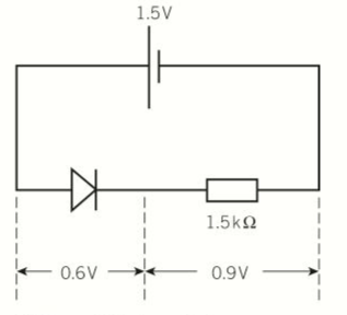
- The pd across the diode is 0.6V because it is forward biased.
- Therefore the pd across the resistor is 0.9 V (=1.5V-0.6V)
- Current through the resistor is therefore 0.6 x 10⁴ (=0.9V/15000Ω)
- If the diode was revered, the circuit current would be 0.
- Pd across the resistor would be 0, the pd across the diode would be 1.5 V (emf)
13.5 THE POTENTIAL DIVIDER:
The theory of the potential divider:
- A potential divider is made up of two or more resistors in series with each other and with a source of fixed potential difference.
- The pd of the source is divided between the components in the circuit as they are in series with each other.
- By making a suitable choice of components, a potential divider can be used to:
- Supply a pd which is fixed at any value between zero and the source pd.
- To supply a variable pd.
- Supply a pd that varies with physical conditions such as temperature or pressure.
- By making a suitable choice of components, a potential divider can be used to:
To supply a fixed potential difference:
- Considering two resistors: R1 and R2 in series connected to a source of pd (V0) as shown below:
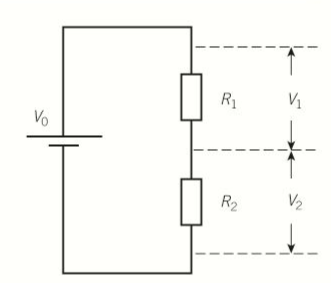
- The total resistance =R1+R2.
- Current through the resistors is:
- PD (V1) across the resistors R1 is given by:
- PD (V2) across the resistor R2 is given by:
- The two equations show that the pd across each resistor as a proportion of the source pd is the same as the resistance of the resistor in proportion to the total resistance.
- In other words, if the resistance are 5KΩ and 10KΩ:
- Pd across the 5KΩ is 1/3 of the source pd.
- Pd across the 10KΩ is 2/3 of the source pd.
- Dividing the equation for V1 by the equation for V2 gives you:
- This equation shows:


The ratio of the pds across each resistor is equal to the resistance ratios of the two resistors.
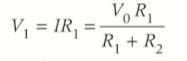
To supply a variable potential:
- The source pd is connected to a fixed length of uniform resistance wire.
- A sliding contact on the wire can then be moved along the wire.
- Giving a variable potential between the contact and the other end of the wire.
- A uniform track of a suitable material may be used instead of resistance wire.
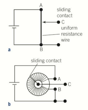
- Track may be linear or circular as shown below:
- The circuit symbol for a variable potential divider is also shown below:
Uses for a potential divider:
- A simple audio volume control to change the loudness of sound from a loudspeaker.
- The audio signal pd is supplied to the potential divider to place of a cell or battery.
- Variable output pd from the potential divider is supplied to the loudspeaker
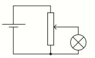
- To vary the brightness of a light bulb from zero to normal brightness.
- In contrast with a variable resistor in series with the lightbulb and the pd source, the use of a potential divider enables the current through the lightbulb to be reduced to zero.
- If the variable resistor in series with the light bulb had been used, there would be a current through the light bulb when the variable resistor is at maximum resistance.
Sensor circuits:
- A sensor circuit produces an output pd which changes because of a physical variable like temperature and or light intensity.
- Temperature sensor:
- Consists of a potential divider made using a thermistor and a variable resistor like below:
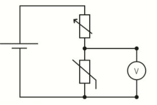
- With the temperature of the thermistor constant, the source pd is divided between the thermistor and the variable resistor.
- By adjusting the variable resistor, the pd across the thermistor can then be set at any desired value.
- When the temperature of the thermistor changes, its resistance changes so the pd across it changes, when the variable resistor is adjusted so that the pd across the thermistor at 20ºC is exactly half the source pd.
- If the temperature of the thermistor is then raised, its resistance falls, so the pd falls.
- A light sensor:
- Uses a LDR and a variable resistor, as shown below:
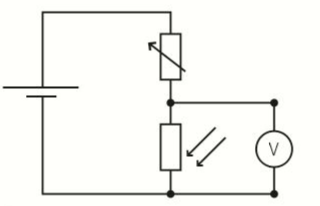
- The pd across the LDR changes and when the incident light intensity changes.
- If the light intensity increases, the resistance falls, and the pd across the LDR falls.
